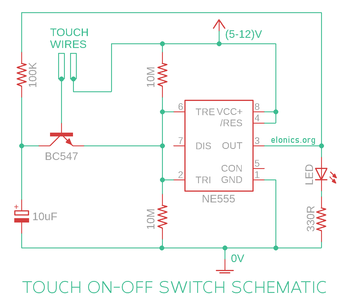
Capacitor values above 100uF may produce inaccurate results because leakage in the capacitor becomes comparable with its charging rate.

Resistor values below 10k are undesirable, as they increase power consumption.Resistor values below 1k should not be used.and $C$ is the capacitance is microfarads.If we want a pulse duration differnt then are given in a table, we can use a simple formula, !Q - negated output of the flip-flop (opposite to Q).īelow a table with pulse duration dependence (in seconds) on resistance and capacity combination are given.!R1 - master reset - low state turns off Q output regardless of the state of the other two inputs,.R - reset - high state sets Q output to low state,.S - set - high state set Q output to high state,.The functions of its oins are as follows: In 555 chip SR flip-flop is used to remember the output states of voltage comparators.

The R = S = 1 combination is called a restricted combination or a forbidden state because, it breaks the logical equation Q = !Q (which is a consequence of internal structure, where two NOR gates are used). If S is pulsed HIGH while R is held LOW, then the Q output is forced HIGH, and stays high when S returns to LOW similarly, if R is pulsed HIGH while S is held LOW, then the Q output is forced LOW, and stays LOW when R returns to LOW. In case of SR, while the R and S inputs are both LOW, feedback maintains the Q and !Q outputs in a constant state, with Q the complement of !Q. Right image: S=0, R=0 preserve previous state. We can push a button to turn light on, and the circuit will automatically switch it off after a predefined time. It can be used for an automatic light off. Next for a predefined time output switch to high state and after that goes to low until another "impuls". The output of the circuit stays in the low state until there is a trigger input, hence the name "monostable" meaning "one stable state". This type of circuit produces one pulse of a defined length in response to a trigger input such as a push button.

In some sense, the 555 itself is unable to do anything constructive - it has to be accompanied by other elements, chips or circuits.


 0 kommentar(er)
